


In order to optimize the scientific exploitation of JET (Joint European Torus) during the upcoming deuterium-tritium experiments, a set of diagnostic systems is being enhanced. These upgrades focus mainly on the experimental and operational conditions expected during tritium campaigns. It should be stressed that measurements relevant for burning plasmas are specifically targeted. Previously non-available capabilities, such as a current measurement system fully covering all poloidal field circuits, are described in detail. Instrument descriptions, performance prediction, testing, and initial commissioning results of these systems are presented.
I. INTRODUCTION
The upcoming JET deuterium-tritium (DT) campaign, DTE2, is scheduled to take place before the end of 2020. For many years, JET diagnostics have been upgraded in order to provide adequate support for scientific exploitation, with particular attention to the experimental and operational conditions expected during deuterium-tritium campaigns.1–3 Diagnostic capabilities relevant to burning plasmas conditions have been specifically targeted.
II. DIAGNOSTICS UPGRADE FOR OPERATION
The currents flowing in the 9 poloidal field circuits (P1, PFX (Poloidal Field for X point formation), P4, Imbalance, Shaping, and D1–D4) are currently measured by three different technologies.4 Current measurement drifts have appeared over the years and not properly recalibrated, originating a discrepancy between two similar measurements of about 6%. Even with a proper calibration, some diagnostics such as “shunts” and Rogowski coils (in the integrator part) suffer, for example, from temperature sensitivity, which can change strongly during the campaigns. If the measurements are inaccurate (offsets), there is conflicting information (between current and magnetic measurements) for the evaluation of the plasma current profile, which leads to inconsistencies between the EFIT (Equilibrium Fitting code)5 reconstructed poloidal field currents and the poloidal field currents measured during the discharge. Regarding the poloidal field currents acquisition system, it would be useful to have a better temporal resolution since a strong coupling between the plasma and P1 coil means that high currents can be induced during a disruption. The early phase of the current quench lasts less than 10 ms at JET and sees the rise of electromagnetic forces as well as runaway electron beams. A better time resolution for P1 current measurement would improve understanding of the conditions in which runaway electrons are created. Another important motivation to acquire the poloidal field power supplies current, with high precision and good temporal resolution (>2.5 kHz), is to understand how the central solenoid and the other poloidal field currents drive the recovery of the plasma current between ELMs and possibly to understand better how the plasma current suddenly changes as a consequence of an ELM (Edge Localized Modes). These measurements would provide a better evaluation of plasma stored energy inter-ELM (Wp/Wdia) and the quantification of its drop after an ELM.
To address these issues, open-loop, open-path, Hall effect current measurement sensors will be installed fully covering all poloidal field circuits. Imaging capabilities have become an important tool both operationally and for the protection of plasma facing components. An optical relay system has now been put in place, and initial data (Fig. 1), for both the wide angle6 and divertor7 fields of view, have been obtained during system commissioning, guaranteeing operability prior to plasma operations.

The equipment of the core active charge exchange diagnostic system, essential for a quality increase of the ion temperature measurements, has now been put in place.8
III. DIAGNOSTIC UPGRADES FOR NEUTRON DETECTION
A 12-pixel Single Crystal Diamond (SCD) matrix has been developed and installed in the JET roof laboratory (radial line of sight).9 The SCD neutron spectrometer has been developed for 14 MeV neutron measurements in DT plasmas where it offers very high energy resolution (about 1% FWHM) combined with a high counting rate capability (>1 MHz). Measurements of 2.5 MeV neutrons from DD (Deuterium-Deuterium) reactions have shown that basic neutron spectroscopy can be performed also for the 2.5 MeV neutrons. A single pixel SCD was installed earlier in the beam dump of a neutron spectrometer10 (with an oblique line of sight). Following this installation, good 2.5 MeV data were collected which have proven that the SCD can provide useful information on the neutron spectrum. In particular, the diagnostic can provide information on non-thermal neutron emission caused by Ion Cyclotron Resonance Heating (ICRH). This will complete the information provided by the spectrometers installed with a radial line of view [TOFOR (Time-Of-Flight neutron spectrometer at Optimized Rate), diamond matrix and NE21311,12] and an oblique view (NE213), which is important in order to measure the anisotropicity in the distribution function of the heated fuel ions. SCD spectrometers observing the neutron emissions from different lines of sight in future D, TT (Tritium-Tritium), and DT campaigns will allow for better separation of the neutron spectral components [due to thermal Neutral Beam Injection (NBI) and ICRH]. In DT plasmas, the SCD neutron spectrometers will provide information on thermal/non-thermal neutron emission, ICRH fast ion tails, and possible ion temperature. The installation of a remote controllable high voltage power supply and a digitizer capable of real time analysis of the pulses will provide the capabilities needed for operations in the coming high power D, TT, and DT campaign. The expected neutron spectra for a SCD in this position are shown in Fig. 2.

Expected neutron spectra with different components during the JET DT campaign for the SCD in oblique line of sight.
Expected neutron spectra with different components during the JET DT campaign for the SCD in oblique line of sight.
SCD has shown to have good resolution (Fig. 3) and spectral capabilities able to distinguish source composition. The results shown on Fig. 4 are measurements obtained with a SCD to monitor the generator used for 14 MeV neutron calibration at JET.


ToFu is a fully digital upgrade of the data acquisition system (DAS) for the TOFOR neutron spectrometer13 at JET. The ToFu system offers considerable simplification and enhancements of the performance of the spectrometer, with higher data quality and improved physics analysis. The improved physics possibilities include improved background suppression that makes the spectrometer sensitive to even weaker emission components in the spectrum, thereby improving the possibilities for studies of ICRH and MHD physics, as well as exotic neutron production channels. The sharper response function opens up for simultaneous measurements of the weak DD emission in DT dominated plasmas. Thus, investigation of ITER-relevant methods for fuel ion density ratio determination will be possible, along with the potential to disentangle the behavior D and T sub-populations in DT plasmas. Implementation of new on-line data acquisition and reduction modes, in particular in DT, could increase considerably the total number of events per shot that the system can store, thus improving the statistical accuracy of the measurements. At present, the ToFu system is limited to 20 acquisition channels with some of the 37 detectors of the TOFOR spectrometer having to share channels. Furthermore, it is dependent on control signals supplied from the TOFOR DAS system. Therefore the ToFu system will be expanded to equip every detector with its own acquisition channel while integrating it into JET data acquisition and control systems. This will make the system truly independent of the TOFOR DAS, data will become commonly available, and system overall reliability will increase. The simulated response functions of TOFOR and fully digital (ToFu) acquisition systems are shown in Fig. 5. The long tails characteristic of TOFOR for both 2.5 and 14 MeV neutrons are tackled by ToFu.
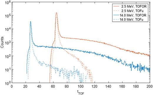
Simulated response functions of TOFOR and fully digital (ToFu) acquisition systems.
Simulated response functions of TOFOR and fully digital (ToFu) acquisition systems.
Initial data obtained with the Bicron BC418 detectors14 of the neutron cameras, after installation of the new digital acquisition system, show the triton burn up signal added through a set of pulses for statistical purposes (Fig. 6).

Bicron BC418 triton burn up experimental signal data added through set of pulses.
Bicron BC418 triton burn up experimental signal data added through set of pulses.
IV. DIAGNOSTIC UPGRADES FOR ALPHA PARTICLES
JET has an excellent set of confined alpha-particle diagnostics, which comprise gamma-ray spectrometers, KM6S-1 (vertical view), KM6S-2 (vertical view), and KM6T (quasi-tangential view) for measuring energy distribution of fast ions and a 2D neutron/gamma-ray camera for tomographic reconstruction of the alpha-particle source and the temporal evolution of its spatial emissivity.15 The feasibility of alpha-ray measurements depends on efficiency of the neutron suppression. Also, it is important to avoid carbon-containing materials in the neutron attenuator because the inelastic scattering of neutrons with energy exceeding 5 MeV, 12C(n,n’gamma)12C, leads to the unwelcome background of 4.44-MeV gamma rays. The best neutron attenuator is 6LiH, but LiH with a natural Li composition could be used as well. It is compact, effective, and well transparent to MeV gamma-rays. It does not produce interfering gamma-rays in the high-energy range. A 30-cm sample of the 6LiH-filter reduces the 2.5-MeV neutron flux ≈900 times and the 15-MeV neutron flux ≈30 times. The attenuator has been tested in JET experiments with deuterium plasmas. Assessments of the gamma-ray background reduction in the energy range below 3 MeV gave a factor of 100. A small reduction of the spectra (factor of 2) was found in the energy range above 3 MeV, due to the Gamma-ray transparency of the 6LiH-attenuator. The KM6S-1 detector (JET Octant 8) with a LaBr3(Ce) scintillator is viewing the plasma centre vertically through 2-m collimators. A similar detector, KM6S-2 (JET Octant 5), is permanently recording the spectra viewing the plasma centre through a 30-cm 6LiH attenuator. For the DT operation, an additional 30-45 cm LiH attenuator is needed for alpha-particle measurements in DTE2. A new LiH attenuator will be installed inside the existing Stainless Steel (SS) collimator (after suitable modifications). In Fig. 7, the position of the detector and attenuator relative to the JET vessel is shown.

The gamma camera16–18 results have been obtained for gammas generated by runaway beams (Fig. 8). This has been done with the CeBr3 prototype detectors (the final detectors use LaBr3 crystals) that were installed before the beginning of the last experimental campaigns. This provides support for upcoming studies both at JET and internationally.19–21

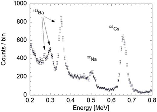
All the CsI detectors have now been replaced with LaBr3. The increased capabilities of the system now allow measuring calibration sources that were previously not detected (see Ba peaks in Fig. 9).
CeBr3 and LaBr3 proved to have very similar characteristics with the decision to choose LaBr3 being mainly due to the intrinsic activity this crystal has. This fact can be useful for calibration purposes. The obtained spectra of the LaBr3 intrinsic activity is show on Fig. 10.

V. INSTABILITIES DIAGNOSTIC UPGRADES
At JET, the edge electron density profile can be measured by a Li beam diagnostic (schematic of the system in Fig. 11) along a vertical line (R = 3.252 m) in octant 7 × 24 spatial channels with resolution of 1 cm (mapped onto the midplane).

The reduction in the existing Li beam current wobbling, by removing the ring transformer from the soft iron shield and re-arranging the heating cables, will be essential for blob investigation by reducing an intense frequency peak in the spectral region of interest for such studies and allow a faster and safer replacement of the ion gun, which could be performed in ½ h rather than 2 h. In this way, reducing the exposure of staff to high activation after high level NBI discharges and T experiments would minimize the impact on JET operation time, reduce the power losses in the transformer chain, and provide increased operational space of the heating, which would extend the useful operation time of the ion gun. Furthermore, ELMs can have a significant impact on the detected background light levels. Thus, this should be monitored, i.e., beam chopping is needed for background measurements on time scales of interest. For JET, pedestal analysis inter ELM profiles are typically requested. Considering the maximum repetition frequency of ELMs (e.g., in the case of high gas injection), beam chopping should be carried out with 10 kHz frequency (at present, this can only be performed up to 100 Hz). The increase in the current output to ≈100 mA will be achieved by two new power supplies and further slight modifications to the system will allow chopping with 10 kHz frequency and with only microsecond long rise time. Other upgraded diagnostics such as the TAE (Toroidal Alfvén Eigenmodes),24 the Fast Lost Ion Detector25 and reflectometry systems26 have already obtained experimental results during the last campaigns.
ACKNOWLEDGMENTS
With this set of diagnostics, JET is in the process of concluding an enhancements programme that has prepared this device for upcoming DT campaigns. This work has been carried out within the framework of the EUROfusion Consortium and has received funding from the Euratom research and training programme 2014-2018 under Grant Agreement No. 633053. The views and opinions expressed herein do not necessarily reflect those of the European Commission.

